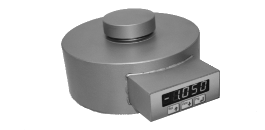
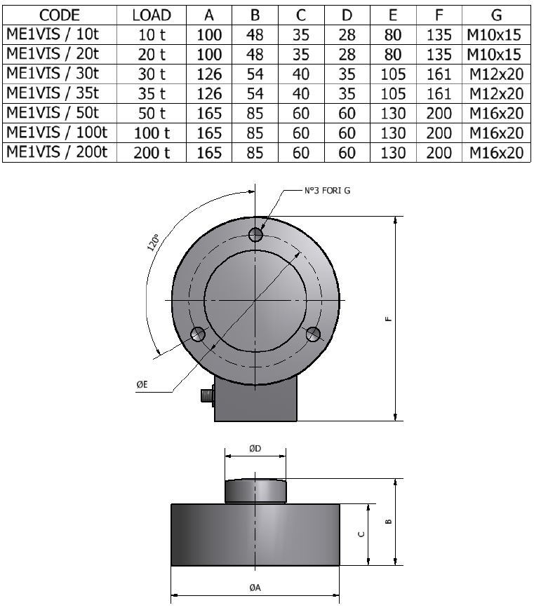
The new ME1VIS compression load cells have the ability to view directly on the load cell the value of the applied load. Through a built-in indicator ME1VIS is capable to display applied load, set filters, set the peak and linearize load points.
Testes and calibrations performed in COMPRESSION with the dynamometer mounted on a bearing support with correctly tightened clamping screws.
EN61000-6-2, EN61000-6-3, EN61010-1
![]() Click to enlarge image
Click to enlarge image


| Material | Stainless steel |
| Nominal load | 10, 20, 30, 35, 50, 100, 200 t |
| Limit load | 150 % F.S. |
| Breaking load | 300 % F.S. |
| Nominal load deflection | 0.06 mm |
| Supply voltage | 5 - 13 V dc |
| Max absorption | 1.5 W |
| Linearity | 0,05 % F.S. |
| Hysteresis | 0,03 % F.S. |
| Reapeatability | 0,02 % F.S. |
| Input resistance | 700-710 Ohm |
| Output resistance | 700-705 Ohm |
| Thermal compensation | -10 / +50°C (14 / +122°F) |
| Operating temperature | -20 / +50°C (-4 / +122°F) |
| Temperature deviation zero | 0,003 % F.S. / °C |
| Temperature deviation full scale | 0,002 % F.S. / °C |
| Protection class | IP 40 |
| Display | 5 digit red led |
| Mechanical keypad | 3 mechanical keys |
| Internal resolution | 24 bit |
| Digital filter | 0.1 Hz - 50 Hz |
| Fixing screws: resistance class | 12,9 |
| Fixing screws: tightening torque | 10-20t: 70 Nm, 30-35t: 125 Nm, 50-200t: 300Nm |
| Standard cable length | 5 m – Power supply connector M12 5P (shield not connected to the load cell body) |
| Type | Power connector M12 5P |
| Length | 5 m (body lead cell not connected shield) |
| 1 | + IN |
| 2 | - IN |
| 3 | RS485 - OPTIONAL |
| 4 | RS485 + OPTIONAL |
General precautions to be followed in the installation and assembly of load cells: